Product range

RF & microwave components, DC to 110 GHz

A complete catalog of coaxial connectors, adapters, terminations, attenuators, DC blocks, waveguide transitions and insulators — with custom and OEM configurations built to drawing.

Home/Product Range
01 — Coaxial connectors

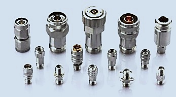
RF Coaxial Connectors

Precision 50 Ω coaxial connectors in male and female configurations, covering standard, miniature and millimeter-wave interfaces. Available in straight, right-angle, bulkhead, flange and panel-mount styles with solder, crimp or PCB attachment.

✓

Full interface coverage

N, TNC, TNC-A, BNC, BMA, SMA, SSMA, SMP, APC-7, 3.5 mm, 2.92 mm, 2.4 mm, 1.85 mm and 1.0 mm series.

✓

Materials

Stainless steel passivated or brass with gold-plated center conductors and PTFE dielectric as standard.

✓

Mounting options

Straight, right-angle, 2-hole and 4-hole flange, bulkhead and PCB surface mount.

✓

Temperature range

Operating range −55 °C to +125 °C for demanding environments.
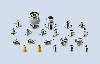
RF coaxial connector range Precision in-series adapters Bulkhead connector series
SeriesFrequencyImpedanceCouplingTypical use
NDC – 18 GHz50 ΩThreadedRugged outdoor & general RF systems
TNCDC – 18 GHz50 ΩThreadedHigh-vibration environments
TNC-ADC – 18 GHz50 ΩThreadedImproved-reliability variants
BNCDC – 4 GHz50 / 75 ΩBayonetInstrumentation & video
SMADC – 27 GHz50 ΩThreadedSub-miniature, high-density RF
SSMADC – 40 GHz50 ΩThreadedCompact microwave assemblies
SMPDC – 40 GHz50 ΩSnap-onBoard-to-board blind mate
BMADC – 18 GHz50 ΩSlide-onRack & panel blind mate
APC-7DC – 18 GHz50 ΩSexlessMetrology & calibration
3.5 mmDC – 33 GHz50 ΩThreadedPrecision laboratory measurement
2.92 mmDC – 40 GHz50 ΩThreadedPrecision test to 40 GHz
2.4 mmDC – 50 GHz50 ΩThreadedMillimeter-wave instruments
1.85 mmDC – 65 GHz50 ΩThreadedMillimeter-wave test & systems
1.0 mmDC – 110 GHz50 ΩThreadedHighest-frequency measurement

Model nomenclature

Our connector part numbers follow a structured code, so you can identify the interface, polarity and mounting style directly from the model number.

Code blockMeaningAvailable options
D _ _Port type34 = N  ·  36 = 2.92 mm  ·  37 = 2.4 mm  ·  38 = 1.85 mm  ·  39 = 1.0 mm  ·  54 = TNC-A  ·  55 = SMA  ·  57 = SSMA  ·  63 = SMP
D _ polarityPort polarity0 = Jack (female)  ·  1 = Plug (male)  ·  N = genderless
D _ _ MMounting styleS = detachable  ·  M = metal bulkhead  ·  P = dielectric bulkhead  ·  D = airline bulkhead  ·  T = direct-mount  ·  B = PCB solder  ·  L = end-launch
D _ _ _ CCoupling styleF = flange mount  ·  Y = threaded mount  ·  H = PCB vertical solder  ·  E = PCB edge solder
… F01–F13Flange specificationStandard flange patterns F01 to F13 (dimensions available on request)
Example: D55 0 S … F01 decodes as an SMA jack (female), detachable mounting, flange type F01 connector. Tell us the interface, polarity and mounting you need and we will confirm the exact part number.
02 — Coaxial adapters

Adapters

In-series and between-series adapters for laboratory benches, production test stations and system integration. Precision construction maintains impedance continuity and low VSWR across the full operating band.

Bulkhead adapters Right angle adapters Millimeter wave adapters Adapter family

In-series adapters

Male-to-male, female-to-female, right-angle and tee configurations within a single interface family. Ideal for extending test leads and protecting instrument ports.

Between-series adapters

Cross-interface adapters such as N-to-SMA, 2.92 mm-to-2.4 mm, 3.5 mm-to-2.92 mm and APC-7-to-N, covering the common laboratory transitions.

ConfigurationTypical combinationsFrequencyStyle
In-series, straightSMA-KK, SMA-JJ, N-KK, N-JJDC – 27 GHzStraight barrel
In-series, right-angleSMA-KWK, SMA-JWJ, N-KWKDC – 18 GHz90° body
N to SMAN/SMA-KK, N/SMA-JK, N/SMA-JJDC – 18 GHzStraight / bulkhead
N to 3.5 mmN/3.5-KK, N/3.5-JKDC – 18 GHzStraight
N to 2.92 mmN/2.92-KK, N/2.92-JKDC – 18 GHzStraight
3.5 mm to 2.92 mm3.5/2.92-KK, 3.5/2.92-JKDC – 33 GHzStraight, precision
2.92 mm to 2.4 mm2.92/2.4-KK, 2.92/2.4-JKDC – 40 GHzStraight, precision
2.4 mm to 1.85 mm2.4/1.85-KK, 2.4/1.85-JKDC – 50 GHzStraight, precision
1.85 mm to 1.0 mm1.85/1.0-KK, 1.85/1.0-JKDC – 65 GHzStraight, precision
BNC to SMABNC/SMA-KK, BNC/SMA-JKDC – 4 GHzStraight
TNC to SMATNC/SMA-KK, TNC/SMA-JKDC – 11 GHzStraight
APC-7 to NAPC7/N-KK, APC7/N-JKDC – 18 GHzStraight, precision
Part-number convention: within a model code, K denotes a jack (female) interface, J a plug (male) interface, and W a right-angle body. Tell us the interfaces you need and we will confirm the matching part number.
03 — Terminations & loads

Terminations & Loads

Coaxial terminations provide a matched 50 Ω load for unused ports, protecting sources and preserving measurement accuracy. Available across the common interface families, from precision laboratory loads to medium-power units.

TypeInterfacesFrequencyPowerTypical VSWR
Precision termination2.4 mm, 2.92 mm, 3.5 mmDC – 50 GHz0.5 – 1 W< 1.15:1
Precision termination1.85 mm, 1.0 mmDC – 110 GHz0.5 – 1 W< 1.35:1
Standard terminationSMADC – 18 GHz1 – 2 W< 1.20:1
Standard terminationNDC – 18 GHz2 – 5 W< 1.20:1
Medium-power loadN, TNCDC – 12.4 GHz10 – 50 W< 1.30:1
Economy terminationBNCDC – 4 GHz1 W< 1.25:1
Selection note: choose power handling above your expected average power with margin, and select the connector interface that matches your instrument port. When in doubt, send us your operating conditions and we will recommend a part.
04 — Fixed attenuators

Fixed Attenuators

Coaxial fixed attenuators reduce signal level by a precise, repeatable amount. Commonly used to protect instrument inputs, extend dynamic range and match power levels. Attenuation values from 1 dB to 40 dB.

Coaxial fixed attenuator
Part-number seriesInterfacesFrequencyValuesPower
A5510 seriesSMA (m) to SMA (f)DC – 18 GHz3 / 6 / 10 / 20 / 30 dB2 W
A3510 series3.5 mm (m) to 3.5 mm (f)DC – 26.5 GHz3 / 6 / 10 / 20 / 30 dB2 W
A3610 series2.92 mm (m) to 2.92 mm (f)DC – 40 GHz3 / 6 / 10 / 20 / 30 dB2 W
A3710 series2.4 mm (m) to 2.4 mm (f)DC – 50 GHz3 / 6 / 10 / 20 / 30 dB2 W
N-seriesN (m) to N (f)DC – 18 GHz3 / 6 / 10 / 20 / 30 dB5 – 50 W
Decoding the part number: the dB value is the final two digits — L03 = 3 dB, L06 = 6 dB, L10 = 10 dB, L20 = 20 dB, L30 = 30 dB. Example: A3610P1L20 is a 2.92 mm 20 dB attenuator.
05 — DC blocks

DC Blocks

A DC block inserts a capacitor in the RF path, isolating DC while passing the RF signal. Used to protect sensitive instruments from DC bias, separate DC and RF paths, and supply bias without disturbing the RF circuit.

Inner DC block

Blocks DC on the center conductor. The most common type, used to protect spectrum analysers and receivers from DC on the inner conductor.

Outer DC block

Blocks DC on the outer conductor. Used where ground-loop isolation or floating screen conditions are required.

TypeInterfacesFrequencyBlocking voltageTypical insertion loss
Inner DC blockSMA (m) – SMA (f)0.01 – 18 GHz50 V DC≤ 0.6 dB
Inner DC blockN (m) – N (f)0.01 – 8 GHz50 V DC≤ 0.7 dB
Inner DC blockBNC (m) – BNC (f)0.001 – 3 GHz50 V DC≤ 0.5 dB
Inner DC block2.92 mm (m) – 2.92 mm (f)0.01 – 40 GHz50 V DC≤ 0.8 dB
Outer DC blockSMA (m) – SMA (f)0.01 – 18 GHz50 V DC≤ 0.7 dB
Outer DC blockN (m) – N (f)0.01 – 8 GHz50 V DC≤ 0.8 dB
06 — Waveguide transitions

Waveguide-to-Coaxial Transitions

Waveguide-to-coaxial adapters convert between rectangular waveguide and coaxial line, allowing millimeter-wave waveguide components to be connected to coaxial test equipment and instruments.

Waveguide to coaxial transition
Waveguide bandCoaxial interfaceFrequency rangeTypical VSWRInsertion loss
WR-28 (Ka)2.92 mm (m/f)26.5 – 40 GHz1.25:1 max0.4 dB max
WR-22 (Q)2.4 mm (m/f)33 – 50 GHz1.30:1 max0.5 dB max
WR-15 (V)1.85 mm (m/f)50 – 75 GHz1.35:1 max0.5 dB max
WR-12 (E)1.0 mm (m/f)60 – 90 GHz1.35:1 max0.5 dB max
WR-10 (W)1.0 mm (m/f)75 – 110 GHz1.40:1 max0.6 dB max
Materials: connector outer conductor in stainless steel, passivated; center conductor in beryllium copper, gold plated; waveguide body in brass, gold plated. Operating temperature −55 °C to +125 °C.
07 — Feedthrough insulators

Feedthrough Insulators

Single-pin and multi-pin RF feedthrough insulators provide a sealed, impedance-controlled transition through a package wall, carrying RF or DC into microwave modules and hermetic packages.

RF feedthrough insulator
TypeFrequency rangePin diameterPin configuration
Single-pin feedthroughDC – 8 GHz0.23 mm (0.009")ST – ST
Single-pin feedthroughDC – 18 GHz0.30 mm (0.012")ST – ST
Single-pin feedthroughDC – 28 GHz0.38 mm (0.015")ST / RD
Single-pin feedthroughDC – 46 GHz0.45 mm (0.018")ST / RD
Single-pin feedthroughDC – 73 GHz0.46 – 0.51 mmST / RD
Multi-pin feedthroughDC – 18 GHz0.30 – 0.51 mm2 – 8 pin arrays
Pin types: ST = straight pin, RD = round-head pin. Combinations such as ST–ST, ST–RD and RD–RD are available. Multi-pin arrays are configured to customer requirement.
08 — Ferrite components

Isolators & Circulators

Ferrite isolators and circulators provide non-reciprocal signal routing. Isolators protect sources from reflected power; circulators route signals between three ports for duplexing and switching applications.

ProductFormatFrequencyTypical isolationTypical insertion loss
Coaxial isolatorSMA, N1 – 18 GHz≥ 18 dB≤ 0.5 dB
Coaxial circulatorSMA, N1 – 18 GHz≥ 18 dB≤ 0.5 dB
Drop-in isolatorSurface mount2 – 18 GHz≥ 20 dB≤ 0.4 dB
Waveguide isolatorWR-series18 – 40 GHz≥ 20 dB≤ 0.4 dB
Availability: isolator and circulator specifications vary considerably by band and power level. Please send your frequency band and power requirement for a specific recommendation.
09 — Cable assemblies

Cable Assemblies

Custom coaxial cable assemblies built to drawing or to your electrical requirement — with controlled electrical length, defined connector combinations and tested performance.

Semi-rigid assemblies

Formable semi-rigid cable with hand-formed bends, providing stable electrical performance and excellent shielding in fixed installations.

Flexible assemblies

Flexible coaxial cable assemblies for applications requiring repeated movement or simplified routing.

Test-grade assemblies

Low-loss, phase-stable assemblies for VNA and bench measurement, with precision connectors on both ends.

To quote a cable assembly we need: connector types at each end, cable type or diameter, overall length, and any electrical or environmental requirement. Send us a drawing or a description and we will confirm.

Looking for a specific part number?

Our catalog is extensive and only part of it is listed here. Send us the part number, interface combination or specification you need and we will confirm availability and price.

sales@northrf.com Send a detailed enquiry